Uml Class Diagram Visio 2007
Unified Modeling Language (UML) is a standard way to draw software models, sketch out designs, or document existing designs and systems.
Note:If you're using Visio for the web, be aware that UML diagrams are available in Visio Plan 1, but are not available in Visio in Microsoft 365.
In Visio Plan 2 and Visio 2019, you can start with a blank UML template or (in some cases) modify a UML starter diagram.
This subscription version of Visio supports UML shapes conforming to the UML 2.5 specification while also providing you the flexibility to use them as needed in your diagrams.
Class diagrams
Use a class diagram to make a general model of the structure of an application that specifies the system's classes, its attributes and methods, and the relationships between objects.
Create a UML class diagram
Component diagrams
Use a component diagram to partition a system into cohesive components and show the structure of the code itself.
Create a UML component diagram
Deployment diagrams
Use a deployment diagram to show the structure of the run-time system and communicate how the hardware and software elements that make up an application will be configured and deployed.
Create a UML deployment diagram
Sequence diagrams
Use a sequence diagram to show the actors or objects participating in an interaction and the events they generate arranged in a time sequence.
Create a UML sequence diagram
Activity diagram
Use an activity diagram to describe the internal behavior of a method and represent a flow driven by internally generated actions.
Create a UML activity diagram
State machine diagrams
Use a state machine (or statechart) diagram to show the sequence of states an object goes through during its life.
Create a UML state machine diagram
Use case diagrams
In the early stages of a development project, use use-case diagrams to describe real-world activities and motivations. You can refine the diagrams in later stages to reflect user interface and design details.
Create a UML use case diagram
Communication diagrams
Use a communication diagram to show which elements in a system interact with other elements in terms of sequenced messages.
Create a UML communication diagram
Database notation diagrams
Use a database notation diagram to draw a model of a database.
Create a UML database notation diagram
Where is the UML Model Explorer?
If you've built UML diagrams in previous versions of Visio, you might remember using the Model Explorer. Diagrams made with the Model Explorer were locked against editing and some formatting. Beginning with Visio 2013 Professional, there is no Model Explorer. You simply drag the shapes from the stencils provided. The shapes are unlocked and more flexible, so you can change their behavior if needed. Drawings are also more customizable, yet they still meet the UML standard. We're sorry, but this also means that if you have a drawing created with Model Explorer, you can't work with it in newer versions of Visio that don't include Model Explorer.
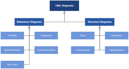
In Visio for the web, you can choose from nine types of UML diagram types and numerous sample diagrams that have some shapes already drawn on the canvas. Each choice comes with a stencil that matches the type of diagram you select.
This subscription version of Visio supports UML shapes conforming to the UML 2.5 specification while also providing you the flexibility to use them as needed in your diagrams.
Class diagrams
Use a class diagram to make a general model of the structure of an application that specifies the system's classes, its attributes and methods, and the relationships between objects.
Create a UML class diagram
Component diagrams
Use a component diagram to partition a system into cohesive components and show the structure of the code itself.
Create a UML component diagram
Deployment diagrams
Use a deployment diagram to show the structure of the run-time system and communicate how the hardware and software elements that make up an application will be configured and deployed.
Create a UML deployment diagram
Sequence diagrams
Use a sequence diagram to show the actors or objects participating in an interaction and the events they generate arranged in a time sequence.
Create a UML sequence diagram
Activity diagrams
Use an activity diagram to describe the internal behavior of a method and represent a flow driven by internally generated actions.
Create a UML activity diagram
State machine diagrams
Use a state machine (or statechart) diagram to show the sequence of states an object goes through during its life.
Create a UML state machine diagram
Use case diagrams
In the early stages of a development project, use use-case diagrams to describe real-world activities and motivations. You can refine the diagrams in later stages to reflect user interface and design details.
Create a UML use case diagram
Communication diagrams
Use a communication diagram to show which elements in a system interact with other elements in terms of sequenced messages.
Create a UML communication diagram
Database notation diagrams
Use a database notation diagram to draw a model of a database.
Create a UML database notation diagram
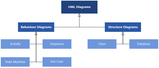
In Visio, you can start with a blank UML template and the appropriate stencil to create your UML diagram.
Class diagrams
Use a class diagram to make a general model of the structure of an application that specifies the system's classes, its attributes and methods, and the relationships between objects.
Create a UML class diagram
Sequence diagrams
Use a sequence diagram to show the actors or objects participating in an interaction and the events they generate arranged in a time sequence.
Create a UML sequence diagram
Activity diagram
Use an activity diagram to describe the internal behavior of a method and represent a flow driven by internally generated actions.
Create a UML activity diagram
State machine diagrams
Use a state machine (or statechart) diagram to show the sequence of states an object goes through during its life.
Create a UML state machine diagram
Use case diagrams
In the early stages of a development project, use use-case diagrams to describe real-world activities and motivations. You can refine the diagrams in later stages to reflect user interface and design details.
Create a UML use case diagram
Database notation diagrams
Use a database notation diagram to draw a model of a database.
Create a UML database notation diagram
Where is the UML Model Explorer?
If you've built UML diagrams in previous versions of Visio, you might remember using the Model Explorer. Diagrams made with the Model Explorer were locked against editing and some formatting. Beginning with Visio 2013 Professional, there is no Model Explorer. You simply drag the shapes from the stencils provided. The shapes are unlocked and more flexible, so you can change their behavior if needed. Drawings are also more customizable, yet they still meet the UML standard. We're sorry, but this also means that if you have a drawing created with Model Explorer, you can't work with it in newer versions of Visio that don't include Model Explorer.
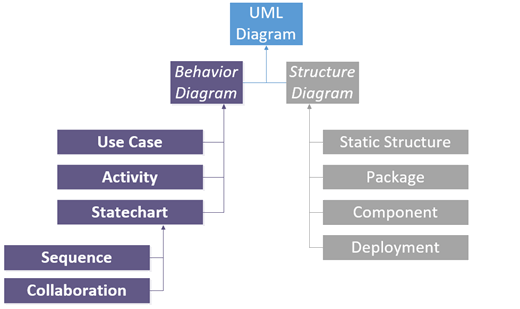
The Microsoft VisioUML Model Diagram template provides full support for creating object-oriented models of complex software systems.
Class diagrams
Use a static structure diagram in Visio to create class diagrams that decompose a software system into its parts.
Create a UML class diagram
Use case diagrams
In the early stages of a development project, use a use case diagram to describe real-world activities and motivations. You can refine the diagram in later stages to reflect user interface and design details.
Create a UML use case diagram
Static structure diagrams
Use static structure diagrams to create conceptual diagrams that represent concepts from the real world and the relationships between them, or class diagrams that decompose a software system into its parts.
Create a UML static structure diagram
Package diagrams
Use package diagrams to group related elements in a system. One package can contain subordinate packages, diagrams, or single elements.
Create a UML package diagram
Activity diagrams
Use an activity diagram to describe the internal behavior of a method and represent a flow driven by internally generated actions.
Create a UML activity diagram
Statechart diagrams
Use a statechart diagram to show the sequence of states an object goes through during its life.
Create a UML statechart diagram
Sequence diagrams
Use a sequence diagram to show the actors or objects participating in an interaction and the events they generate arranged in a time sequence.
Create a UML sequence diagram
Collaboration diagrams
Use a collaboration diagram to show relationships among object roles such as the set of messages exchanged among the objects to achieve an operation or result.
Create a UML collaboration diagram
Component diagrams
Use a component diagram to partition a system into cohesive components and show the structure of the code itself.
Create a UML component diagram
Deployment diagrams
Use a deployment diagram to show the structure of the run-time system and communicate how the hardware and software elements that make up an application will be configured and deployed.
Create a UML deployment diagram
Source: https://support.microsoft.com/en-us/office/uml-diagrams-in-visio-ca4e3ae9-d413-4c94-8a7a-38dac30cbed6
Posted by: otanolianneoes.blogspot.com

Posting Komentar untuk "Uml Class Diagram Visio 2007"